Have you ever dreamed of having a two-story tall, 200-hp, 4-legged, hydraulic mech suit to run around in? I have, so we’re building one. It’s called Prosthesis: The Anti-Robot. This is not a new idea. Many sci-fi movies have depicted machines like this over the years; the legendary Power Loader in Aliens, the menacing Ampsuit in Avatar, and most recently, the absurdly colossal, monster-busting, dual-piloted Jagers in Pacific Rim. While these machines were remarkable and exciting, Prosthesis differs from them in two very crucial ways: 1) it’s real, and 2) it’s built for racing. These two criteria introduce unique challenges in the design of the hydraulic system.

In order to understand the hydraulics, however, we must first understand the application. Prosthesis: The Anti-Robot is a 100% human-controlled, two-story tall, 3,500-kg, 4-legged running machine designed for competitive sport. It is an ongoing educational research project intended to inspire future engineers, designers, and creators while in the pursuit of an entirely new human experience. It is being built by a team of volunteers with the support of industry sponsors, academic partners, and a Vancouver-based educational non-profit called The eatART Foundation that supports the creation of large-scale, technically sophisticated art projects to educate people about alternative energy technology. A CAD rendering is show in Fig. 1.
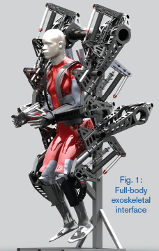
First and foremost, Prosthesis is built for the pilot. Its four massive legs are controlled via a full-body, exo-skeletal interface worn by the pilot (Fig. 1), who is strapped into the center of the machine. Hydraulic power to operate the legs is supplied by electric pumps, driven by a light-weight, 150-kW lithium-ion battery pack. The movement of the legs, including all balancing, running, or (given enough courage) jumping, is entirely up to the skill of the pilot. There are no computers controlling the movement of the machine, no background-stabilizing algorithms, and no auto-pilot. That is why it is called an anti-robot. Robots do things for you; anti-robots leave everything up to the pilot. A machine like this has never been built before, so when tackling the power plant and control system design, we had to think carefully about what we were trying to achieve.
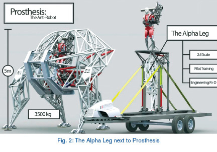
As a platform for development and pilot training, we have built a 2:3 scale prototype leg called the “Alpha Leg.” It is mounted on a hinged tower so it can be dynamically tested and loaded, and eventually ridden. It has a 1 DOF rotary knee joint and a 1 DOF rotary hip joint, both actuated by hydraulic cylinders. The pilot straps his arm into an exoskeletal interface that lets him control the knee with his elbow and the hip with his shoulder. This interface starts out on the ground but can be mounted atop the leg for the next stage of training. Fig. 2 shows it next to Prosthesis for scale.
The most important distinction from its sci-fi counterparts is that it is a real machine, which means there are consequences when something fails or goes out of control. From a hydraulics perspective, this equates to a need for durability, reliability, and stability. Because it is built for sport, however, it has to feel right. This means the controls have to be responsive, light, and ergonomic to deliver the ideal experience to the pilot. Excessive automation and technological intervention are not necessarily the right solution. Prosthesis is a sports machine, and the pilot is the athlete. It would undermine the purpose of the machine to simply hand over the controls to computers.
Putting the human in control has several advantages: 1) it will save us from the robot apocalypse, 2) it creates a rewarding challenge for the pilot, and 3) it takes advantage of the most sophisticated and adaptable control system in the world, the human nervous system. This is often referred to in robotics as “human-in-the-loop-controls.” For a racing machine, the controls must be repeatable and stable enough to master with practice but require low enough input forces that the machine can be operated for at least 20 minutes without excessive fatigue. To start out, we wanted to keep things simple and direct.
First-Generation Interface Pure Mechanical – a Technological Baseline
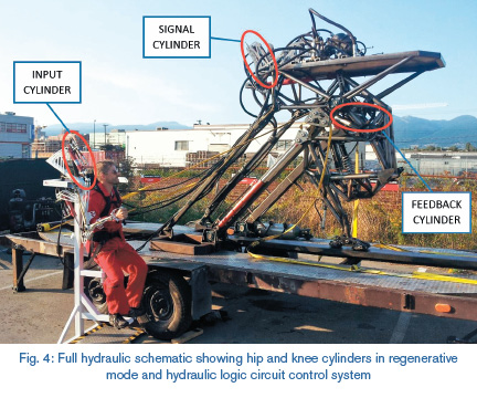
The first incarnation of the control system represents the simplest possible way to achieve the basic positional feedback control system we needed. It used a purely mechanical “hydraulic logic” circuit to control mechanical spool valves, which directed hydraulic power to the working cylinders in the leg. The first-generation exoskeletal interface is shown with the Alpha Leg in Fig. 4.
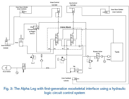
This system used three, small, passive, low-pressure hydraulic cylinders per joint, plumbed in parallel: an input cylinder attached to the exo-frame, a feedback cylinder in the corresponding joint in the leg, and a signal cylinder on the lever of the corresponding spool valve. The schematic of the complete system is shown in Fig. 3.
When the pilot moved his arm, flow would go from the input cylinder on the exo-frame to the signal cylinder on the spool valve atop the platform and open the valve (essentially remotely operating the valve). This would cause the joint on the leg to move and bring the feedback cylinder with it, which would move the signal cylinder on the valve in such a way as to close the valve once the leg joint caught up with the position of the exo-frame. If the pilot wanted to keep the valve open to keep the joint moving, he would have to keep moving his arm. This created a very smooth and stable positional feedback control system with essentially only three moving parts (aside from the spool valve). It was interesting to note that if the feedback cylinder (in the joint) was plumbed directly to the signal cylinder (on the spool valve), resonance and shuddering would occur at certain flow rates. By putting the pilot in the middle of the loop, the feedback signal was sufficiently damped before affecting the valve, creating a stable system across all operating conditions. While functionally very satisfactory, the system suffered from three main problems: a large deadband, limited adjustability, and high input forces.
Second-Generation Interface the Introduction of Electronics – Performance at the Expense of Simplicity
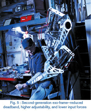
The next-generation control system, shown in Fig. 5, addressed all of these problems by switching to solenoid valves and controllers donated by Hydraforce. This reduced the deadband, introduced many more points and ranges of adjustment, and allowed input forces to potentially be reduced to nearly zero.
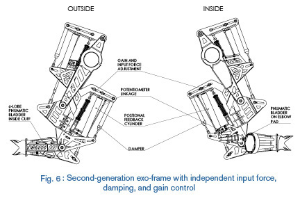
The hydraulic logic circuit was reduced to two cylinders—the input cylinder on the exo-frame and feedback cylinder in the joint on the leg—with the valve transducer connected in series with the input cylinder by a common arm linkage as shown in Fig. 6. Because the input signal was picked up by a rotary encoder, the input force could be as low as desired and was set by adjusting a centering spring. The damping in the system was adjusted through a separate damper. The ratios of all of these elements could be adjusted independently to give the right amount of resistance and stability required for “that sporty feel.” Further, the programmability of the Hydraforce valves gave another point of control to adjust response curves or compensate for factors like user skill and preference and asymmetric cylinder response.
While this more advanced technology solved many of the user experience issues, it is more complex and will require more tuning to reach peak performance. We are presently working with the Hydraforce applications engineers to optimize the system for conditions like overrunning loads and high-differential pressures seen when moving the leg through the air unloaded. There is still work to be done, but the system promises to produce the right combination of performance and usability to be worthy of a sports machine. Once this system is proven to be stable and provide the user experience we want, we will be ready to scale up and build the final, full-scale, 4-legged walking machine, coming in 2015 to a stadium near you!
For more information: Prosthesis is a not-for-profit venture made possible by the generous support from the following organizations: eatART Foundation, UBC Engineering, Emily Carr University of Art and Design, Beakerhead, Hydraforce, PQ Systems, Klassen Specialty Hydraulics, Seastar Solutions, SolidWorks, Lenovo, Sonic Enclosures, Schaffler Canada, Gigavac, Kvaser, UniRope, Design Simulation, Filthy Motor Sports, Praxair, BOSS Audio. If you would like to get involved or contribute as a supporter or donor, please contact Jonathan Tippett, project founder, at Dit e-mailadres wordt beveiligd tegen spambots. JavaScript dient ingeschakeld te zijn om het te bekijken. or visit www.anti-robot.com.
BY FLUID POWER JOURNAL


